Introduction
Until recently a diagnostic procedure, which required access to stored fault codes and other data was only possible with the use of dedicated equipment or relatively expensive code readers or scanners. However, with the proliferation of cars with EOBD/OBD-2 (European/On-Board Diagnostics, version 2) it is possible to extract information from ECUs using a simple interface lead and a standard computer running appropriate software.
Since 1 January 2001, all cars sold in Europe must have on-board diagnostic systems. European Directive 98/69/EC mandated that engine emissions must be monitored. The cars must also be fitted with a standard diagnostic socket.
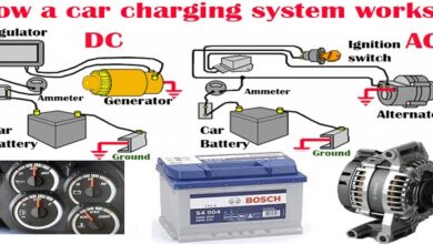
There are three basic OBD-2/EOBD protocols in use, each with minor variations. As a rule of thumb most European and Asian cars use ISO 9141 circuitry as do Chrysler. GM cars and light trucks use SAE J1850 VPW (Variable Pulse Width Modulation), and Fords use SAE J1850 PWM (Pulse Width Modulation) communication patterns.
Reading an EOBD/OBD2 DTC
The first character of the code relates to the system of the vehicle that generated the code:
P = Powertrain
B = Body
C=-Chassis
U = Network
The next character can be either 0 or 1
0 = Standard (SAE) OBD code
1 = Manufacturer’s own code
The next character identifies the specific part of the system concerned. For the Powertrain systems these are:
- Fuel and air metering
- Fuel and air metering, specifically injector circuit
- Ignition system and misfire detection
- Auxiliary emission controls
- Vehicle speed control and idle control system
- Computer output circuit
- Transmission related faults
- Transmission related faults
For example, the code P0115 would indicate an ‘Engine Coolant Temperature Circuit Malfunction’.
Equipment Available
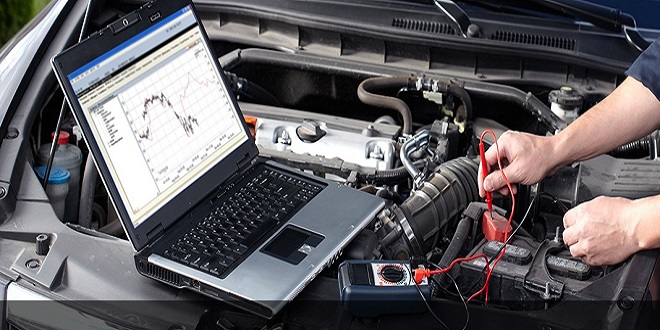
The only equipment needed is a simple interface cable that connects the diagnostic socket to a serial port on the computer. This usually contains a custombuilt circuit that uses surface mount semiconductors that are designed for interfacing an automotive ECU to a PC. An extension lead can be used to allow connection to a PC that is bench mounted. A good design feature to look out for is that the earth or ground pins in the DLC plug are longer than the others.
A number of computer programs are available that will ‘translate’ the DLC signals into a readable format. One particularly good and reasonably priced program is ‘Vehicle Explorer’ created by Alex C. Peper. As well as displaying DTCs this program allows monitoring of sensor signals in both numerical and graphical formats.
Summary
Unfortunately, even though a common standard has been developed some manufacturers have interpreted it in different ways. However, it is now possible to access detailed information from many vehicle systems that until recently was only available to the main dealers.