Introduction
The ‘current’ demands made by modern vehicles are considerable. The charging system must be able to meet these demands under all operating conditions and still ‘fast charge’ the battery.
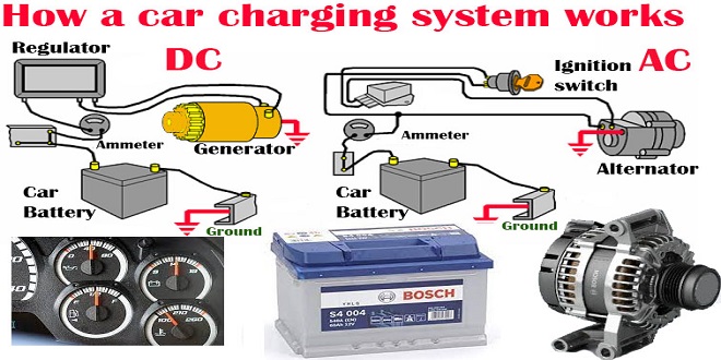
The main component of the charging system is the alternator and on most modern vehicles – with the exception of its associated wiring – this is the only component in the charging system. Figure 6.1 shows an alternator in common use. The alternator generates AC but must produce DC at its output terminal as only DC can be used to charge the battery and run electronic circuits. The output of the alternator must be a constant voltage regardless of engine speed and current load.
Vehicle electrical loads
The loads placed on an alternator can be considered as falling under three separate headings: continuous, prolonged and intermittent. The charging system of a modern vehicle has to cope with high demands under many varied conditions.
To give some indication as to the output that may be required, consider the power used by each individual component and add this total to the power required to charge the battery. The current draw (to the nearest 0.5 A) at 14 and 28 V (nominal; alternator output voltages for 12 and 24 V systems) is also given for comparison.
Charging system principles
When the alternator voltage is less than the battery (engine slow or not running for example), the direction of current flow is from the battery to the vehicle loads. The alternator diodes prevent current flowing into the alternator. When the alternator output is greater than the battery voltage, current will flow from the alternator to the vehicle loads and the battery.
From this simple example it is clear that the alternator output voltage must be greater than the battery voltage at all times when the engine is running. The actual voltage used is critical and depends on a number of factors.
Charging voltages
The main consideration for the charging voltage is the battery terminal voltage when fully charged. If the charging system voltage is set to this value then there can be no risk of overcharging the battery. This is known as the constant voltage charging technique. The chapter on batteries discusses this issue in greater detail.
The other areas for consideration when determining the charging voltage are any expected voltage drops in the charging circuit wiring and the operating temperature of the system and battery. The voltage drops must be kept to a minimum, but it is important to note that the terminal voltage of the alternator may be slightly above that supplied to the battery.
Alternators and charging circuits
Electromagnetic induction is caused by a rotating magnet inside a stationary loop or loops of wire. In a practical alternator, the rotating magnet is an electromagnet that is supplied via two slip rings. The stationary loops of wire are known as the stator and consist of three separate phases, each with a number of windings. The windings are mechanically spaced on a laminated core (to reduce eddy currents), and must be matched to the number of poles on the rotor.
Alternators and charging circuits
Electromagnetic induction is caused by a rotating magnet inside a stationary loop or loops of wire. In a practical alternator, the rotating magnet is an electromagnet that is supplied via two slip rings.
Star connection can be thought of as a type of series connection of the phases and, to this end, the output voltage across any two phases will be the vector sum of the phase voltages. Current output will be the same as the phase current. Star-wound stators therefore produce a higher voltage, whereas deltawound stators produce a higher current.
Last word
There is still plenty of room for improvements in belt-driven alternators for motor vehicles. A combination of longtime experience, modern development methods and innovative production processes has enabled development engineers at Bosch to achieve dramatic gains in alternator performance compared to conventional models – a 35% increase in power density to 1.43 watt per cubic centimetre, a rise in maximum operating temperature from 105 ° C to 120 ° C, and an increase in the maximum degree of efficiency to 76% (VDA average 72%). The developers also succeeded in lowering operating noise by a clearly perceptible 5 dB(A). The result is the new Bosch LI-X range of alternators.